Fuel Injection Systems 101
I imagine there are those who think an electronic fuel injection (EFI) system is totally alien, possibly even sacrilegious! So the following is a fuel

injection 101 to try and demystify things a little. In a basic system, we need seven things: 1. A fuel rail and injectors: The fuel rail acts as a pressurised “float bowl”, providing a reserve of fuel behind the injectors. Injectors, to me, is a bit of a misnomer as it makes them sound like syringes that “push” the fuel into the engine. Actually, the injectors are simply electrically controlled valves that switch on and off and high speed. When they are energised, they open and the pressurised fuel in the fuel rail flows flows through the injector into the manifold. The ECU (see below) is able to control how long the injectors remain open down to a resolution of 0.1ms (0.0001 seconds) allowing for very precise control of the volume of fuel flowing during the cycle. 2. A means of sensing engine load/demand: Either a manifold air pressure (MAP) sensor or a throttle position sensor. Fairly self-explanatory, these measure the pressure (vacuum) inside the manifold and the angle of the throttle respectively. 3. A means of sensing the engine speed (rpm): On my setup this is done by sensing the trigger pulse from the distributor/coil, via some signal conditioning circuitry. 4. A high pressure fuel system: Carbs only require a few psi pressure, whereas an injection system requires a much higher pressure (typically 43.5 psi, 3 bar) to push the fuel through the injectors and in

the process atomise the fuel. So a new pump, a pressure regulator, a low pressure return to the tank and all the associated plumbing is needed. 5. An electronic control unit (ECU). The ECU is simply a small, specially designed, computer and what makes the system EFI rather than just FI! For example, the TR6 PI (petrol injection) system, was without the E, as it was controlled by mechanical means, not by a computer. 6. A manifold to hang everything off. 7. Some wires to link all the electrical bits together. With this we could run the engine if we already had a well defined fuel map. A map is the term used for the settings and equations contained within the ECU - relating the load, engine speed and fuel requirements together. However, we add a few more sensors to expand the range of control we have and allow easier tuning: 1. A manifold air temperature (MAT) sensor, for measuring the temperature and thus density of the air entering the engine. 2. A coolant temperature sensor, to allow the ECU to calculate and control the warmup enrichment requirements, effectively replacing the choke. 3. A wideband lambda sensor (also known as an O2 sensor). Which “sniffs” the composition of the exhaust gases and is thus able to tell how rich or lean the engine is running. This is where the system comes into it’s own, using all these sensors and the clever computer software the whole system is able to self learn how
much fuel it needs and continues to adjust itself for maximum performance for any given speed and load.
Where to Start?
The build sort of started in the summer of 2019, as I started sketching out detailed plans and accumulating parts. Parts were mostly found through eBay, sorting price low to high and looking for bits from cars that were of similar power output (at last check, I had 101hp at the crank, but I have built in head room to go up to 120). The throttle was from a rover K-series engine, the injectors from a Land Rover V8, the temperature sensors are Ford, it is fuelled by a Bosch-a-like fuel pump, and a controlled by a Speeduino ECU. As the plumbing, wiring and manifold were all going to have to be custom made, and the software/ECU can be calibrated to work with whatever it is given, the mis-match of parts wasn’t ever an issue.


Breaking Ground
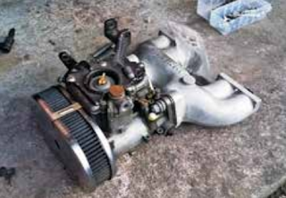
Probably the most pivotal part of the project was the manifold, as it is what everything else attaches to and the interface between the new system and the old engine. I was able to draw up the flange in a CAD (computer aided design) package and have it laser cut from stainless steel. The rest of the manifold was fabricated from various sizes of stainless steel tubing. The fabrication was a bit rough and ready (I am not really a fabricator!) and done using nothing but a grinder and Dremel for cutting and shaping and gummed together with my 90-amp hobby MIG welder! It was labour intensive and is a bit shoddy looking, but it is functional and kept me entertained during a brief spell of unemployment! Once the manifold was near complete, the strip down of the car began, so I could begin test fitting things. It was a bit of an iterative process, positioning things, finding clashes and reconfiguring until a reasonable and tidy compromise was found.
The Brains Behind the Outfit
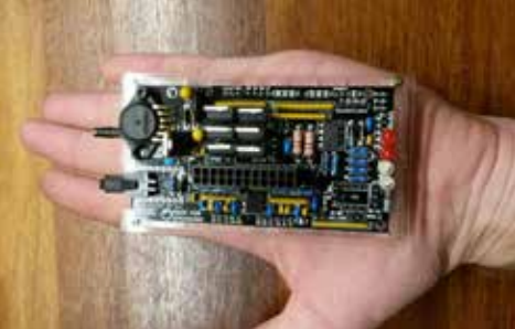
The REALLY clever stuff is contained in the ECU and associated software/programming. Fortunately, the clever boffins in the world have done all the hard work already and wrapped up all the electronics and software stuff into nice easy to use packages. Talking of packages, the ECU itself was a fun mini-project. To keep costs down I bought the self assembly version of the Speeduino ECU. This comes as a box containing about 100 zip look bags of various components and a circuit board. It took a couple of evenings to solder all the tiny components to the PCB (without any real instructions as to what went where!). Another couple of evenings in

front of the computer allowed me to test the basic functions. Amazingly, it all worked first time! The ECU connects to a laptop via a USB cable in order to tune and alter settings. Settings can be changed whilst the engine is running, which makes it extremely flexible and easy to tune and once things are right, the settings can be permanently written to the ECU and the laptop left at home. To tie all the electrical gubbins together I had to make a loom. I found this very enjoyable to make and it took a few evenings work. Not difficult with the right tools but you can’t rush it. A lot of people are scared by electrical/electronic systems. Which is understandable, as you can’t see it working. But I look at it differently. I find them strangely therapeutic to construct, work with and trouble shoot. You have to be very methodical with electrical circuits. You can’t bodge them - they don’t work like that, and problems have to be solved with “intelligence” because the problem isn’t usually immediately visible. Power for the new systems is controlled through a pair of fused relays and a new six way blade fuse box. I think I have to be careful driving at night for the time being, because I have calculated that with all the additional electrical loads I am near the limit of the original alternators power output. Having lights on might tip me over the edge!
The Birth, Teething Problems and Refinements!
With everything welded, soldered, plumbed, wired and bolted together, the first start was rather uneventful! Turn the key and it worked, albeit a little rough! After the adrenalin had subsided I was able to dial in a reasonable idle and have a few runs up and down the road. Even without much tuning the engine was super smooth, lively and tractable.
After that, so the theory goes, you plug in a laptop and hit the “Autotune” button and the software optimises the fuelling required based on assumptions that are generally the same for all engines and live data from all the sensors. But practice and theory don’t always align! The first few longer test runs were not entirely successful. Each time I went out, the car started to run increasingly rough after about 20 minutes. The first time I manage to get back and parked up in the garage before it died, the second time, it died whilst I was opening the garage and I had to push it in. The third time (I should have learnt by this point), it coughed and died about 50 metres from home. There were a lot of twitching curtains as I embarrassingly pushed it the remaining distance and into the garage!
I jumped to the conclusion that it was the fuel getting too hot in the rail due to the proximity of the rail to the exhaust manifold and the fuel rail being made of an excellent heat sink material (copper). Therefore, I set about heat wrapping the exhaust and fuel rail. In the process of doing so, I noticed a coolant leak near the heater box, so perhaps this was causing the engine to overheat? Either way, with the leak fixed and the exhaust wrap in place the problem hasn’t recurred and the wrap has noticeably helped under bonnet temperatures. An hours full chat blat, without issue, when it was 30+ degrees, was the proof of that.
The second major problem manifested itself as the car being unwilling to accept high loads and/or high revs without going way lean and popping and banging like the royal artillery regiment! The data logging capability within the software showed that the ECU was continually sensing this lean condition and opening the injectors for longer and longer to try to add more fuel until the injectors were maxed out (always open).
After some over analysis of the data logs I jumped to the conclusion (seeing a theme here?) that I needed bigger injectors. Injectors were purchased and installed and still the same problem! Eh?! Well, long story short – check the basics first. I tested the fuel pump flow rate and it was barely dribbling out of the end of the hose. Certainly not flowing at the pump rated 135 L/hour! The tiny fuel filter I had carried over from the carburettor system was totally clogged and the pump was struggling to keep up with demand. With an injection system, the pump runs constantly at full speed and anything in excessive of three bar pressure and the required flow is recirculated back to the tank via a pressure regulator. This means that the old filter was tryingto cope with filtering about four tanks (135L) of fuel an hour and a whole load of muck was now being washed out of the tank and being caught by the filter. In hindsight it stood no chance. A new, much bigger and purpose designed filter solved this and concluded weeks of frustration and head scratching. The car hasn’t missed a beat since. Finally, I somehow knackered the starter motor beyond redemption whilst trying to set up the starting sequence and idle mixture. It was only 50- odd years old, pah! Rubbish quality Lucas parts!
Driving
Aside from learning something new, the intention of the conversion was to improve the transient response, idle and all round driveability of the car, all things that despite years of messing I never got perfect with the previous DCOE set up. Once the above issues were sorted, the Autotune feature in the software worked brilliantly and the engine got better, smoother and more powerful the more and more I drove it as it constantly refined the fuelling requirements on the fly. Whilst the tuning process is ongoing, it is already a step up from the carburetted setup. Cold starts and running are much improved and general driving is super smooth. The acceleration enrichment curves still needs some work to really perfect the transient responses. But doing so is a little more difficult as I need someone to drive the laptop whilst I drive the car!
I would like to get it on a rolling road at some point to see how it compares to the old system. I don’t expect to see much change in the headline figures, but it will be interesting to do the comparison. From there I plan for a few more engine enhancements to try to bump power up to 110+ hp, including adding a fully mapped ignition and a lumpier camshaft. With precise electronic control of the fuelling and ignition timing I hope that even with a big, lumpy cam, I won’t lose out too much in terms of low speed driveability. Or maybe I could just whack a turbo on it! :-) If you would like more details on the project, I did a short series of youtube videos on the technical details of the setup, search for “Midget 1500 Fuel Injection”. Or, drop me a message via Facebook.
Cheers, happy Spridgeting!
Malc Le Chevalier